Log Book
Wednesday 03-10-2018: Just before 16:00 I ordered my JTM45 kit from ToneFactory for 555,- euro. Within minutes I received the build manual (which I’ve stored in Dropbox). A layout and schematic was not present. ToneFactory also did not have one, but provided me with with close matches. I found that the build-your-own-clone versions were even closer.
Might check if ToneFactory can get a hi-res version, as they might get the kit there.
Thursday 04-10-2018: Around 12:00 the kit arrived. After some inspection it became clear some parts weren’t delivered. A quick response on a mail to ToneFactory stated that they would sent the missing parts. See PartList. The screw, nuts, etc. where nowhere close and the manual was also not clear.
Friday 05-10-2018: I fixed to mechanical parts to the chassis (excluding front and back) to see if I could figure out which screws and nuts I was missing.
Saturday 06-10-2018: Eventually I went to a hardware store and got myself a variety of screws and nuts. I started with an amp cradle to facilitate the build.
Sunday 07-10-2018: I finished the amp cradle. 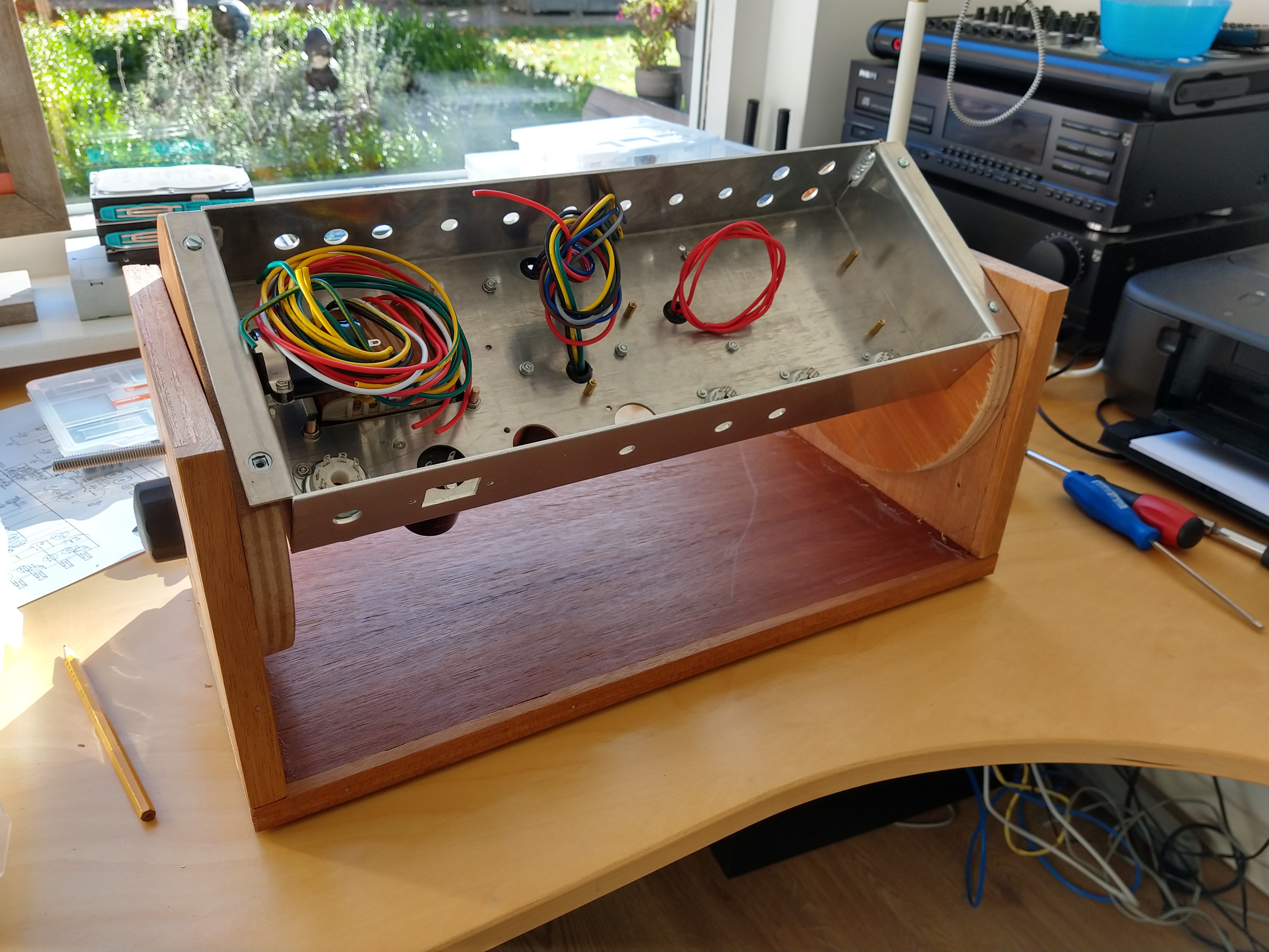 Generated an additional parts list. Das MusikDing has the 2W metal film resistors, 5W 750V Metal Oxide resistors and some handy stuff.
Monday 08-10-2018: Mailed ToneFactory about the missing parts. Created the empty and populated turret board in DIYLC as a preparation for the alterations I’m planning to do. Some of these changes will be: Use the preferred input network as in ‘Designing Tube Preamps for Guitar and Bass’; Move the grid stoppers to the tube sockets; Change the bias supply to the one discussed at the site of Merlin Blencowe.
Tuesday 08-10-2018: DIYLC files are available:
New turretboard is currently rough, but the plan is it will be updated in the future. Also updated layout, links and images of this blog. Also posted it to http://tomkamphuys.github.io .
Wednesday 10-10-2018: Started a thread at TDPRI. Started a schematic.
Thursday 11-10-2018: Band practice.
Friday 12-10-2018: Finished first iteration of schematic.
Saturday 13-10-2018: Received the parts from ToneFactory and installed them. Bias circuit etc. added to schematic.
Sunday 14-10-2018: As I will be using a multiple star grounding scheme (as described in Blencowe’s book), which is different from the manual, I was looking around where I should put the safety-earth. I found no hole for a dedicated screw close to the mains inlet, so I will have to drill that.
I found that the input tube sockets were loose in their chassis mount. They were the shielded version, which I choose for (possible) lower noise. Three chassis clamps without a shield were also supplied and these did clamp the sockets tightly to the chassis.
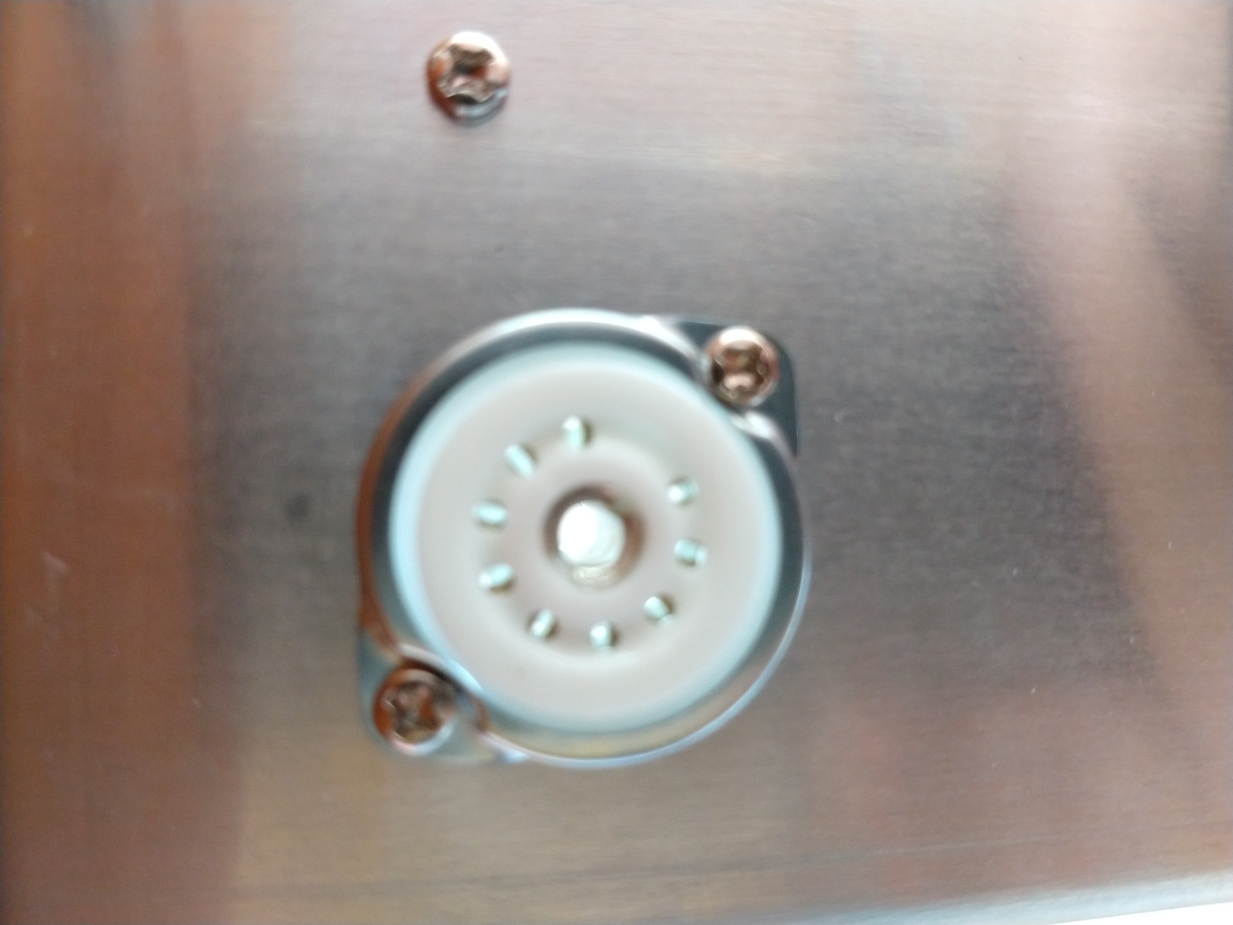
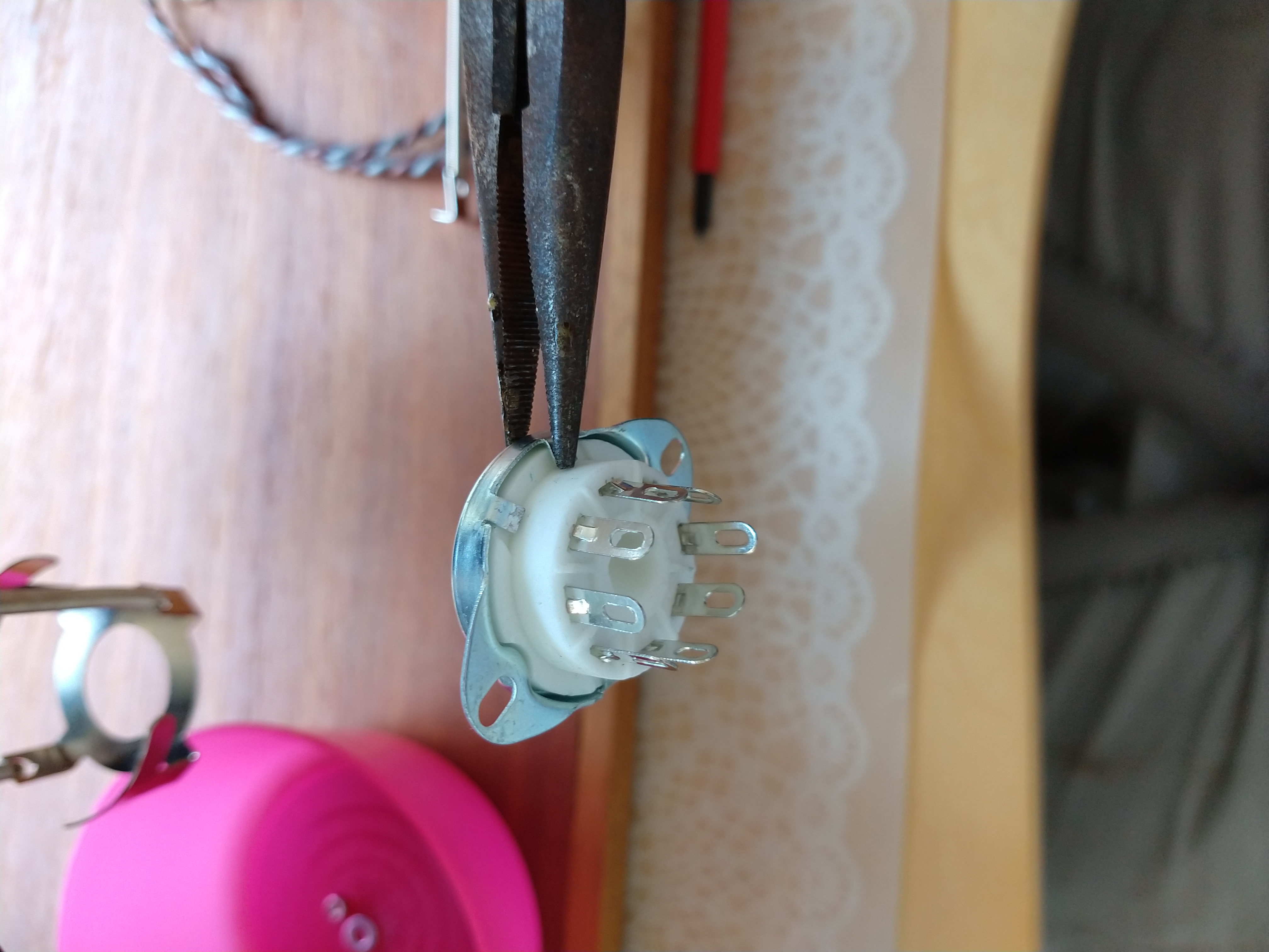
Also the output tube sockets were loose. These have small metal parts that clamp the ceramic socket to the metal chassis mount, which I tightened with a long nose plier.
Looking for resistors.
- Metal film
- Vishay CPF1 1W, 250V, 1%
- Vishay CPF2 2W, 350V, 1%
- Vishay CPF3 3W, 500V, 1%
- Vishay CCF60 1W, 500V, 1%
- Vishay PR03 3W, 750V, 5% (probably). I think these are suitable for the plate load resistors and cathode follower cathode resistor. They need high power and voltage spec (see e.g. Aiken), tolerance is not that important.
- Vishay CMF70 1.75W, 500V, 1%, 0.1uV/V
- Yageo FMP200 2W, 500V, 1%
- Royal Ohm MF200, 2W, 500V, 1%
Tuesday 16-10-2018: Started a thread to get some info about the humdinger placement. Decided to go with the fender chassis mount pots. ToneFactory has both the bias and humdinger pot. Then order the higher voltage elco as well. For resistors Das Musikding seems best.
Wednesday 17-10-2018: Fixed (as in repaired) bias (two errors…) added scale control. Made a diagram in LTSPICE for both the (semi) original version and the my version. Compared Bode plots of original cap values with the smaller ones:
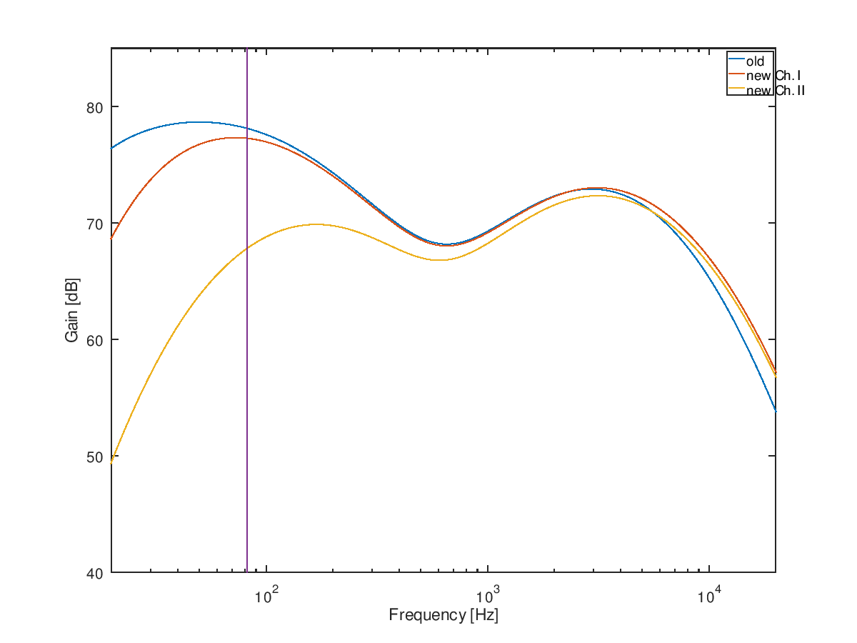
Thursday 18-10-2018: Cathode bypass formula in Choosing Bypass Capacitors is different from Radiotron Designers Handbook Rev. 4 (p. 484). Changed the Matlab/Octave code to represent Radiotrons version. Comparison of the input stages does not make sense. Different behaviour for the LTSPICE model.
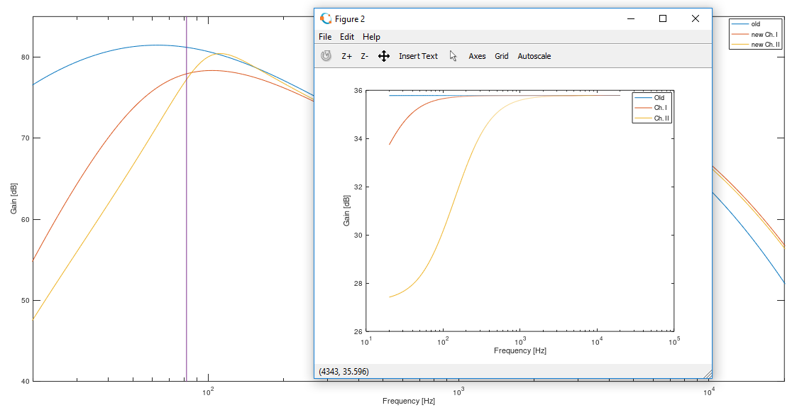
Friday 19-10-2018: I had resistors in the power supply, but no capacitors (and no AC). Removed resistors. Updated BodePlot as seen above (Wednesday). Wrote a script that takes a LTSPICE Bode plot output file and seperates the transfer function for the selected parts of the system.
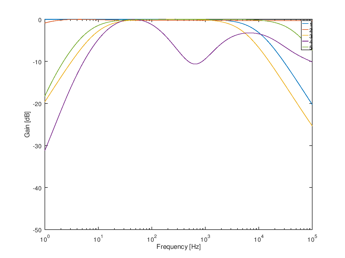
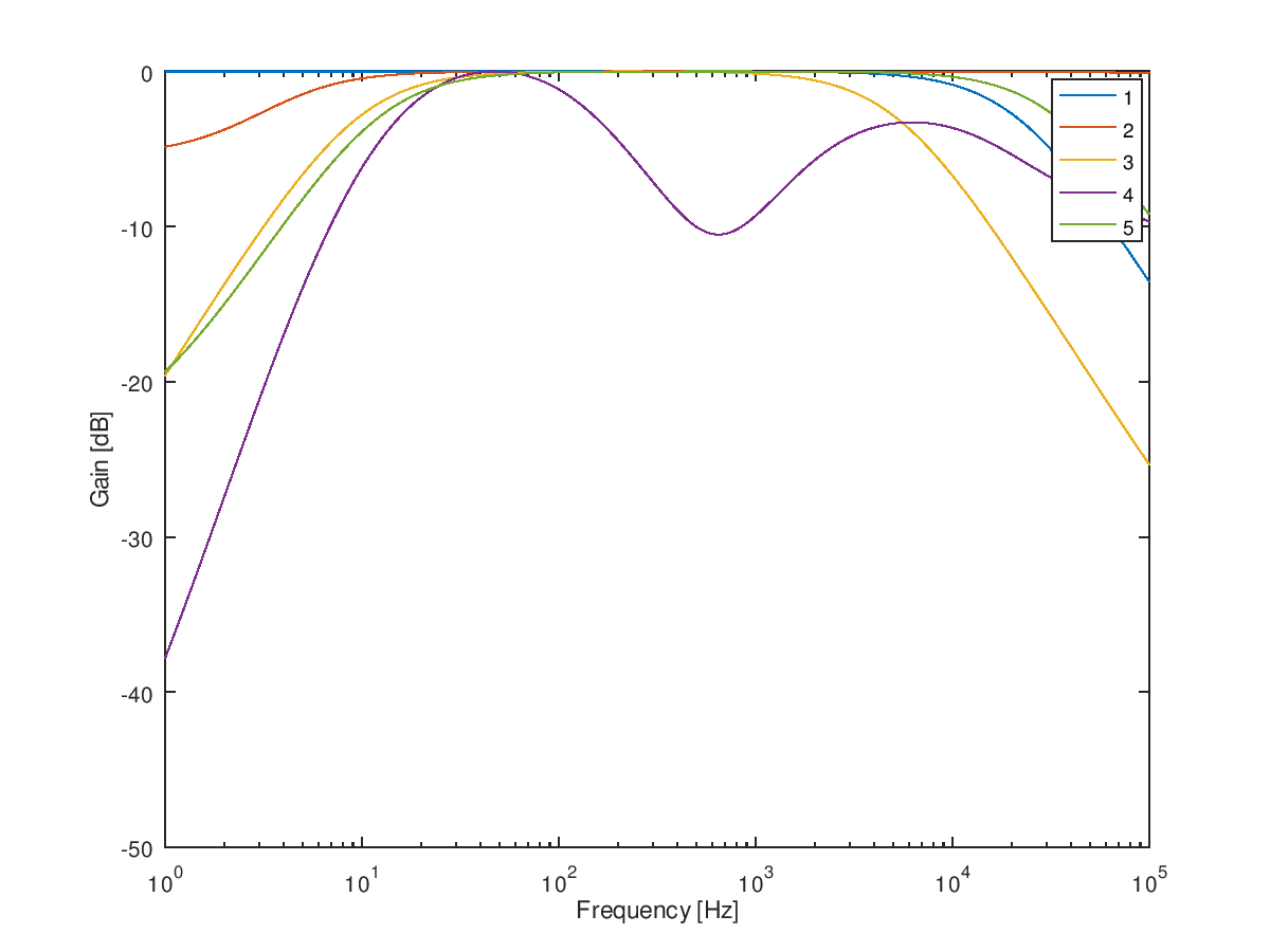
Saturday 20-10-2018: Using the splitCircuit script to analyse, adjusted several caps. Cathode bypass cap changed, but conservatively. Coupling caps around LTPI a bit smaller to limit blocking distortion. First stage should not clip, so left original values in place. Still feel that most could be smaller, but for this first build I’m going to stop here.
| Original | My version |
|---|---|
 |
 |
Sunday 21-10-2018: Don’t know..
Monday 22-10-2018: Finally ordered the parts at MusikDing and ToneFactory.
Tuesday 23-10-2018: Wrote a Grounding Scheme post. I added a turret and a separate wire to the positive star.
Wednesday 24-10-2018: Started with a layout in diylc. It will be a lot of work, but I think it will help in figuring out the grounding scheme. Current version (WIP):
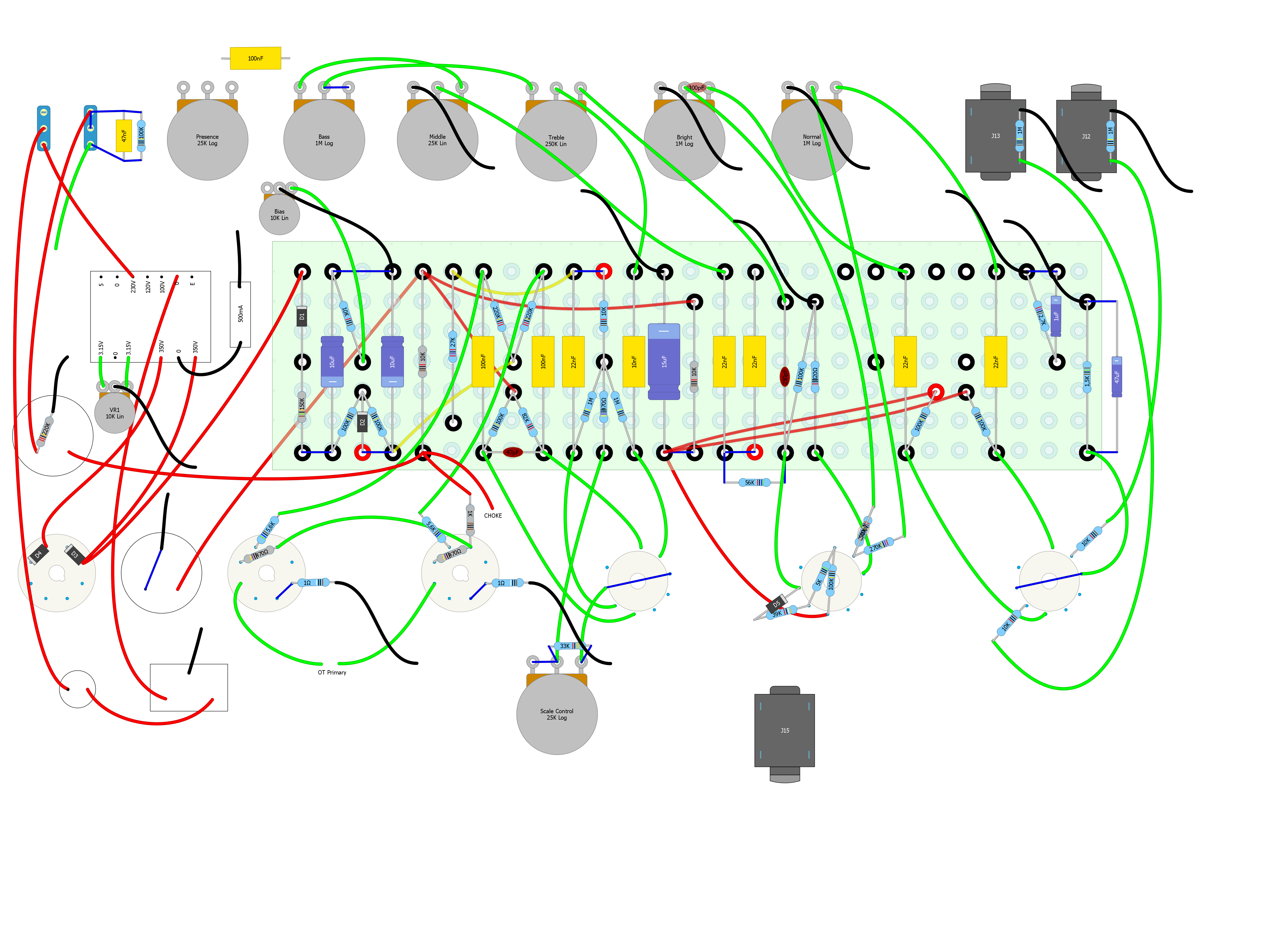 Quite a lot of work has been done. Grounding still has to be done.
Thursday 25-10-2018: Continued with the layout. Don’t know whether strictly following the grounding scheme actually makes a bigger mess of the wiring…
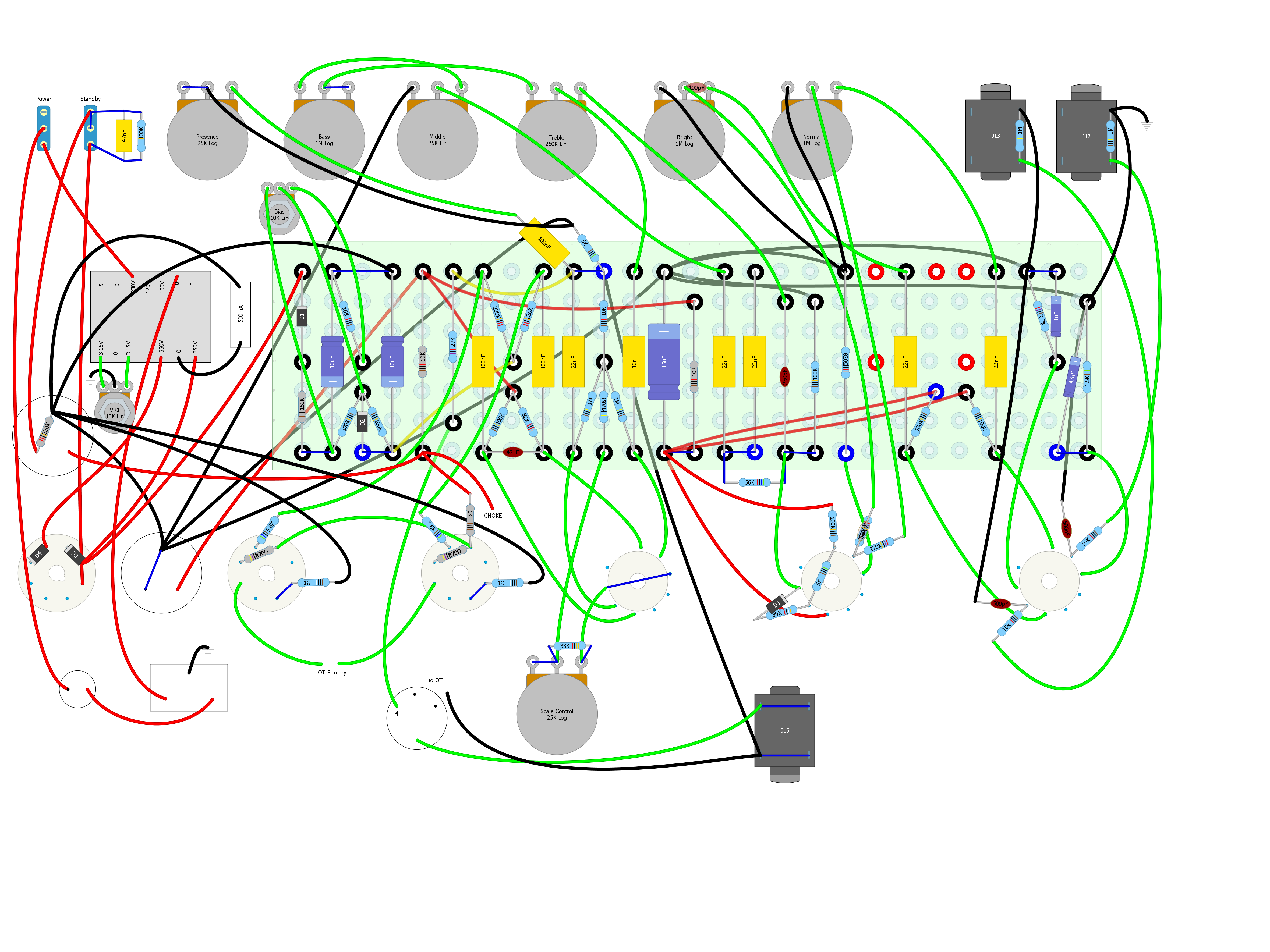
Friday 26-10-2018: Took the liberty to move around some parts to make the star ground cleaner. Looks very similar to Larry’s Grounding Scheme.
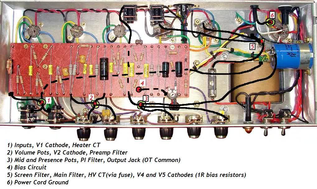
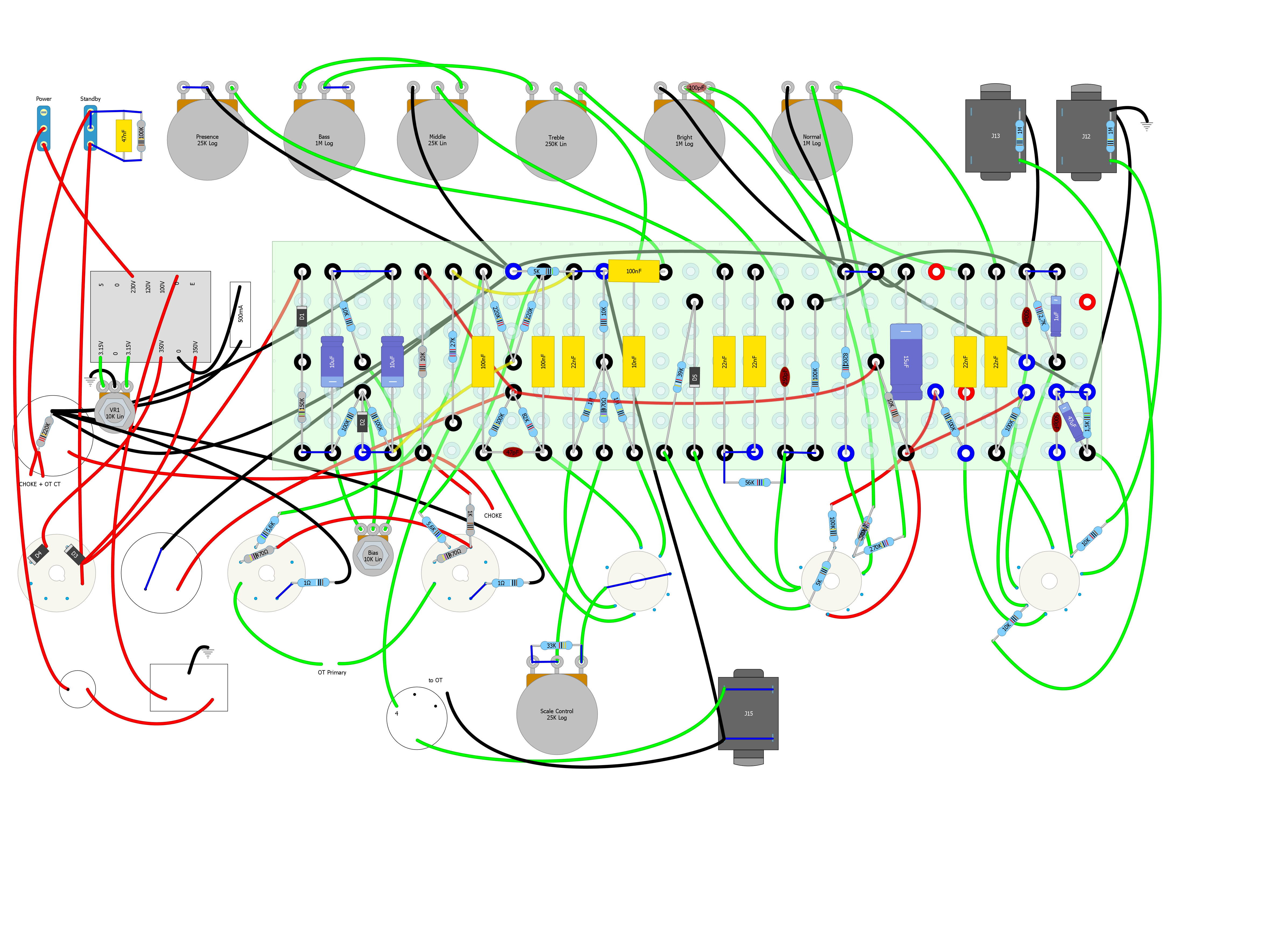
Saturday 27-10-2018: Wrote a blog about the tooling I use/wrote.
Sunday 28-10-2018: Color coded the wires according to 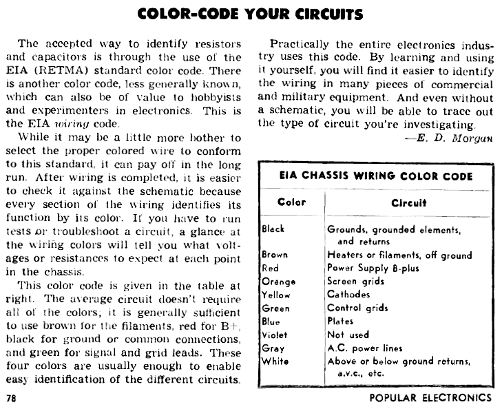 . Power supply (red) and ground (black) override other colors (e.g. cathode follower plate (blue)).
Nice Layout for inspiration:
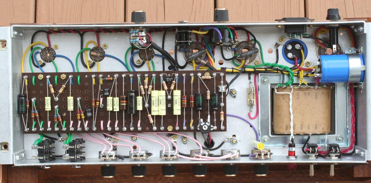
Monday 29-10-2018: Mounting positions of the turret board coincide in two cases with a to be added turret. Need to solve that.
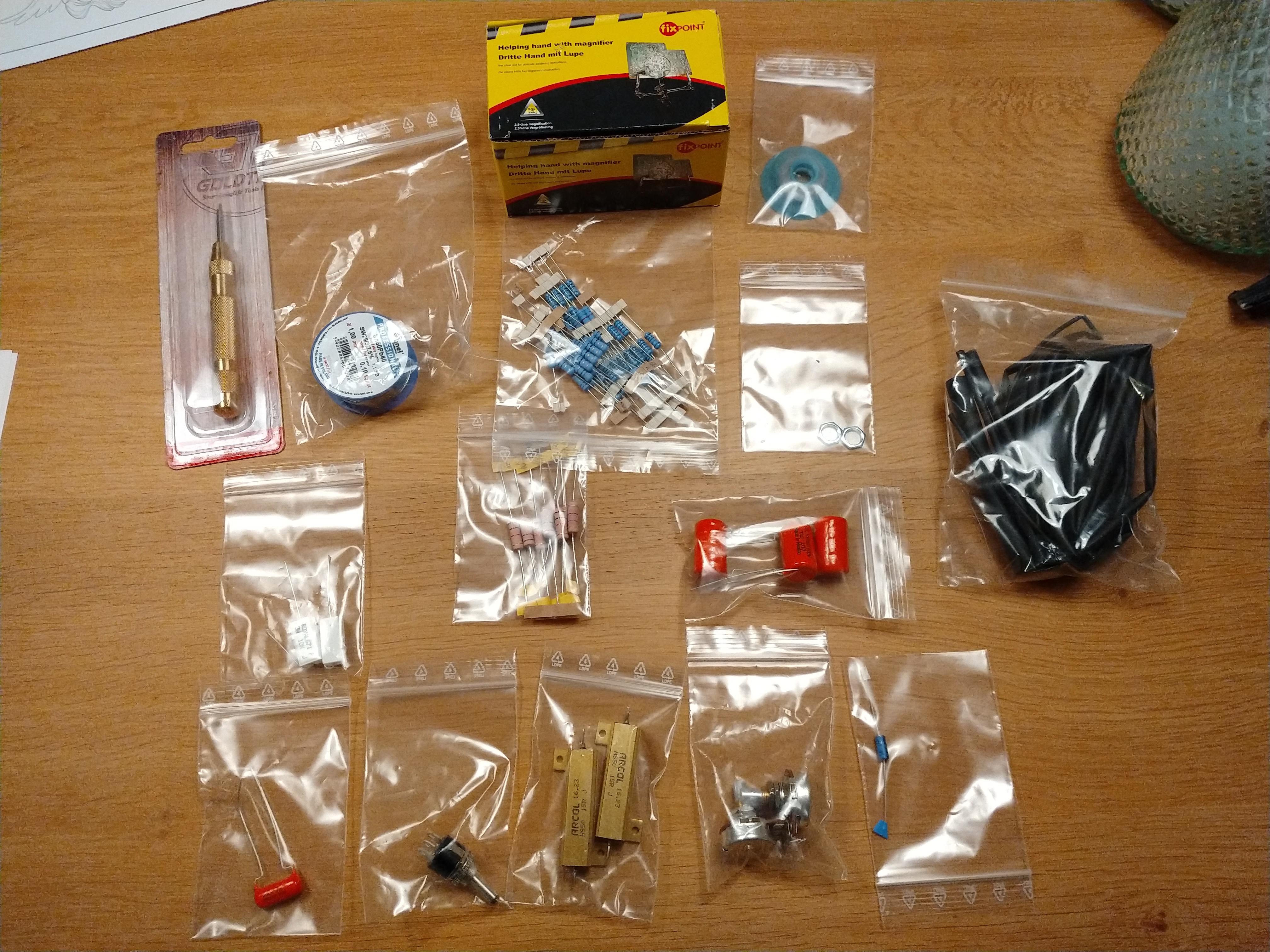
Tuesday 30-10-2018: Parts from Das MusikDing have arived in perfect order. Parts in separate bags and all resistors labelled (value).
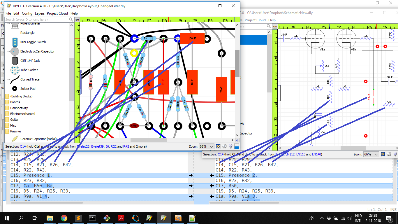
Friday 02-11-2018: Have been quite busy this week writing some software to compare the layout and schematic in DIYLC to each other. It’s starting to look good:
Saturday 03-11-2018: Finally did some work on the amp. Drilled three holes!!! …and mounted the bias pot, humdinger pot and the line chassis ground.
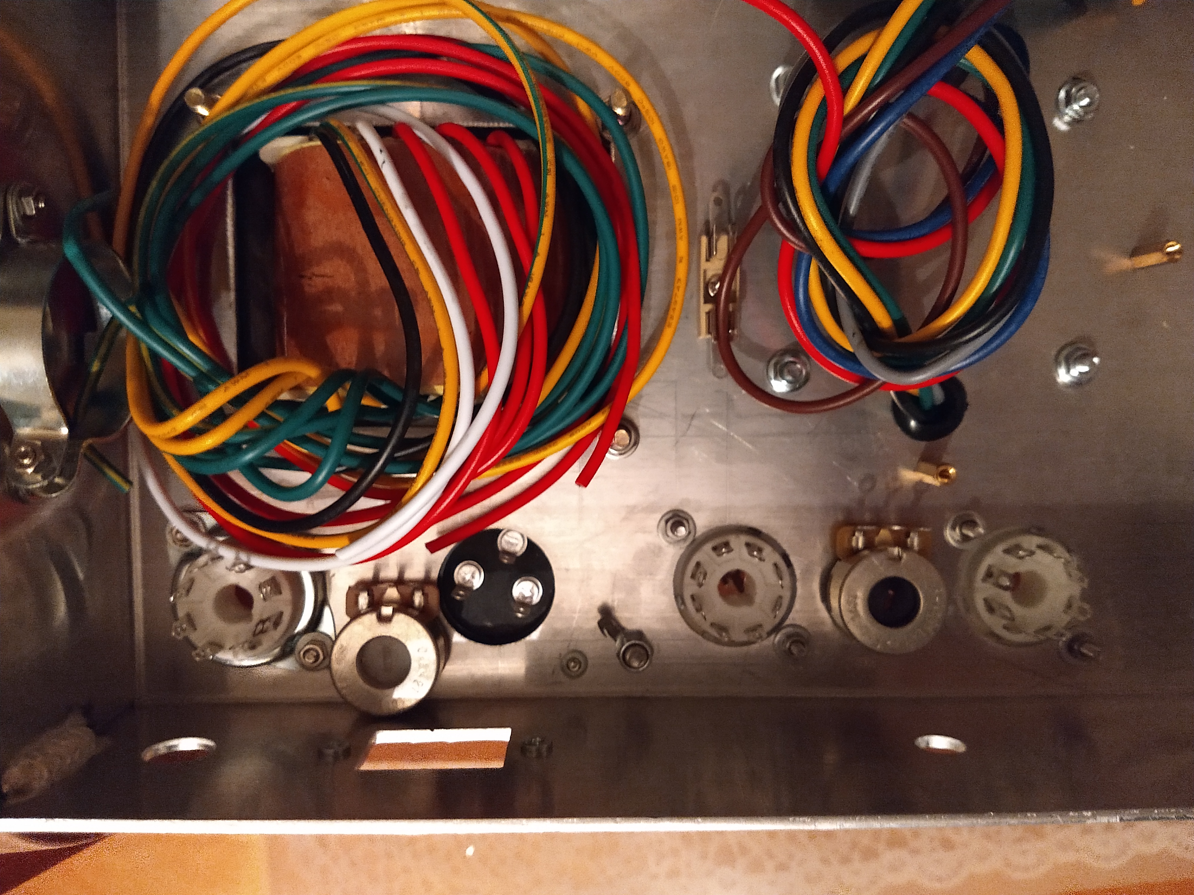
Drilling the holes first with a drill 0.5-1.0mm smaller than the desired hole, seems to help in getting a nice round hole. Had to cut a piece of the cap can holder as it kept the pot from mounting flush to the chassis. Finished the turret mounting tool and mounted one turret. Turret is too long for my turret board… the 3mm must have meant the length and not the diameter.
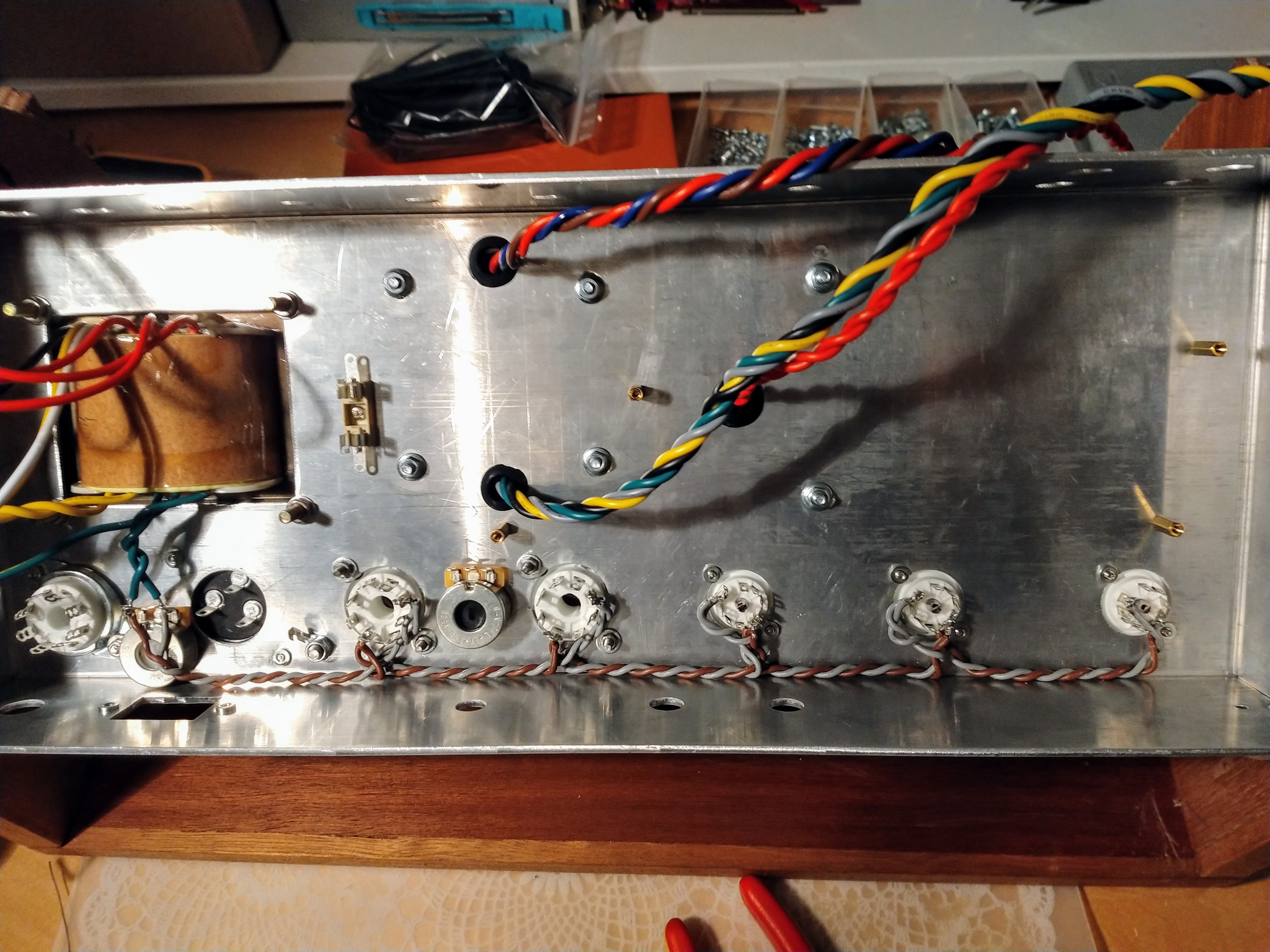
Sunday 04-11-2018: Finally did some soldering. I managed to finish the heater wiring. Getting the two wires into the pre amp sockets was a real PITA.
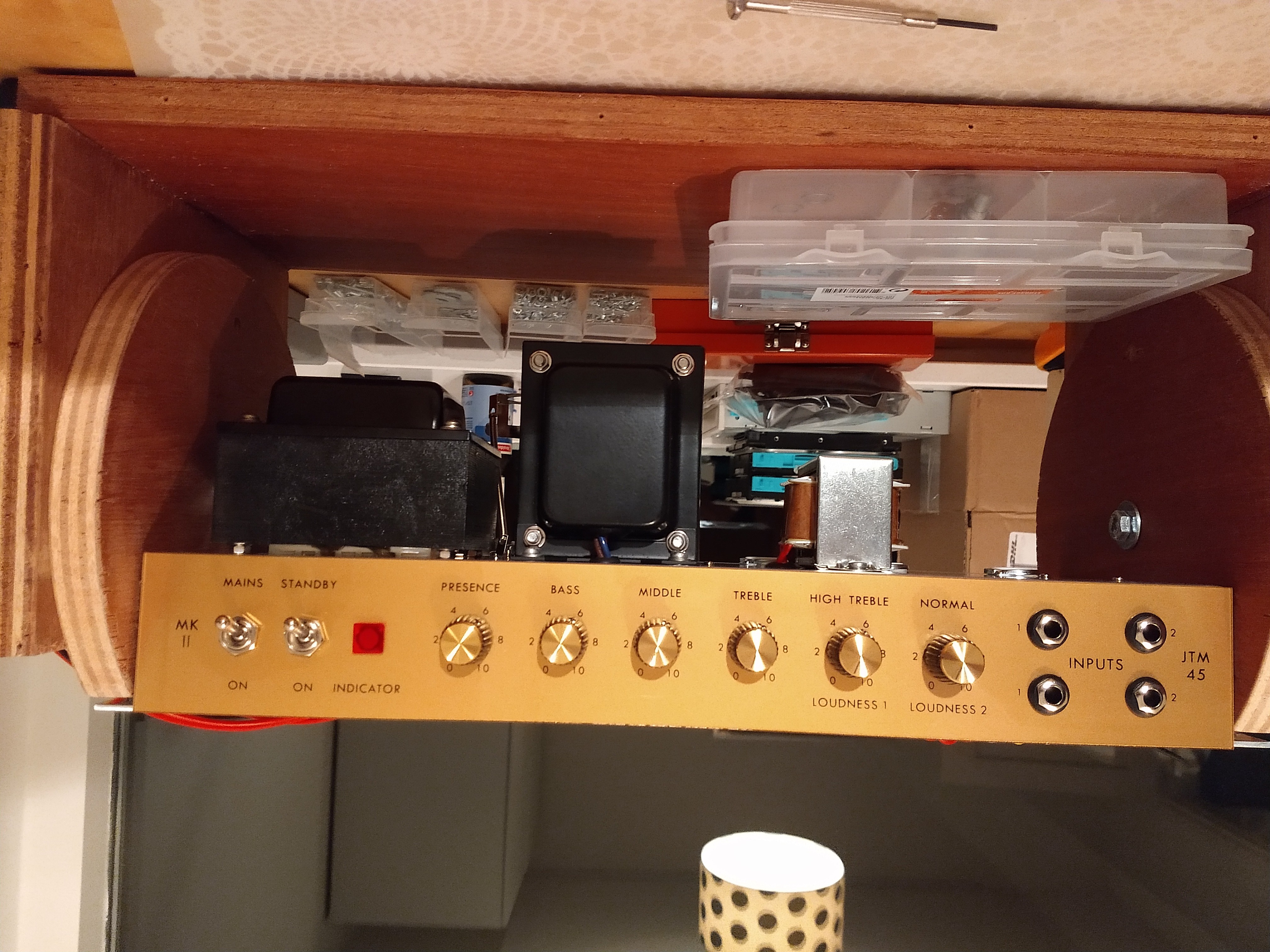
Monday 05-11-2018: Mounted the face plates and all pots, jacks, etc. Looking good:
 .
.
Bourns pots (Scale Control and Presence) feel a bit looser compared to the Alpha pots. Based on feel (alone) I would choose Alpha’s for the future.
Wednesday 07-11-2018: Soldered the heater wire to the rectifier tube. Prepared some more for soldering the various power transformer leads. Did not solder as my soldering iron broke down. Will probably need a new iron.
Removed the standby switch (connections) from the layout. Standby should not be needed and the wires went back and forth the chassis.
Friday 09-11-2018: Borrowed a soldering station from my friend and soldered some more around the power transformer. Probably could have twisted the black and white line wires, but they are neatly parallel and in/near the corner of the chassis. I’m keeping it as they are.
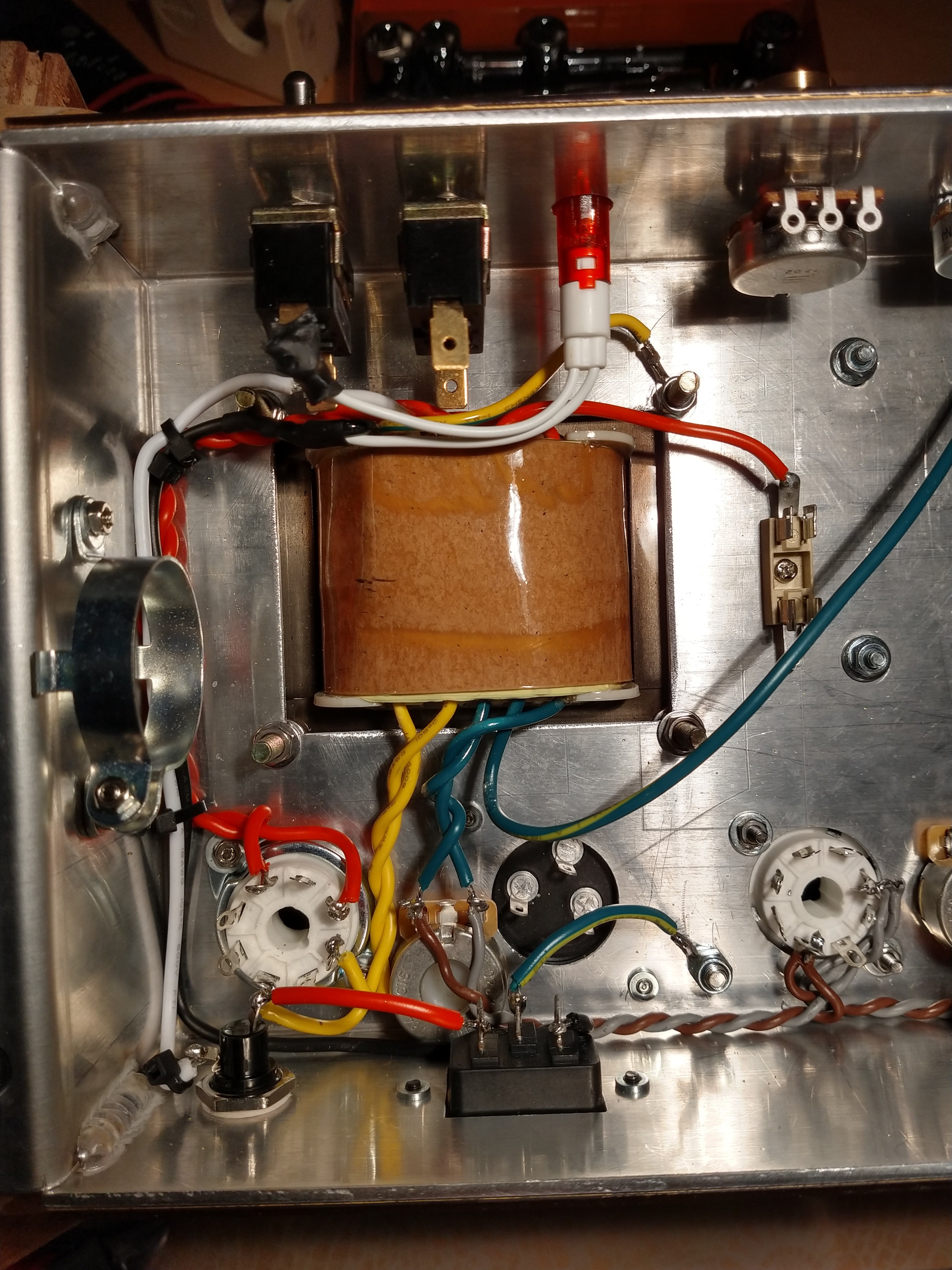
Saturday 10-11-2018: Soldered some more. Adjusted the power transformer wire locations on the layout to be more like the actual transformer used. Started an order at ToneFactory with some wires and plenty of turrets. I plan to use the same color coding for the wires on the amp as in the layout.
Sunday 11-11-2018: Soldered the two diodes at the rectifier tube and the common wire of the impedance selector to the output jack.
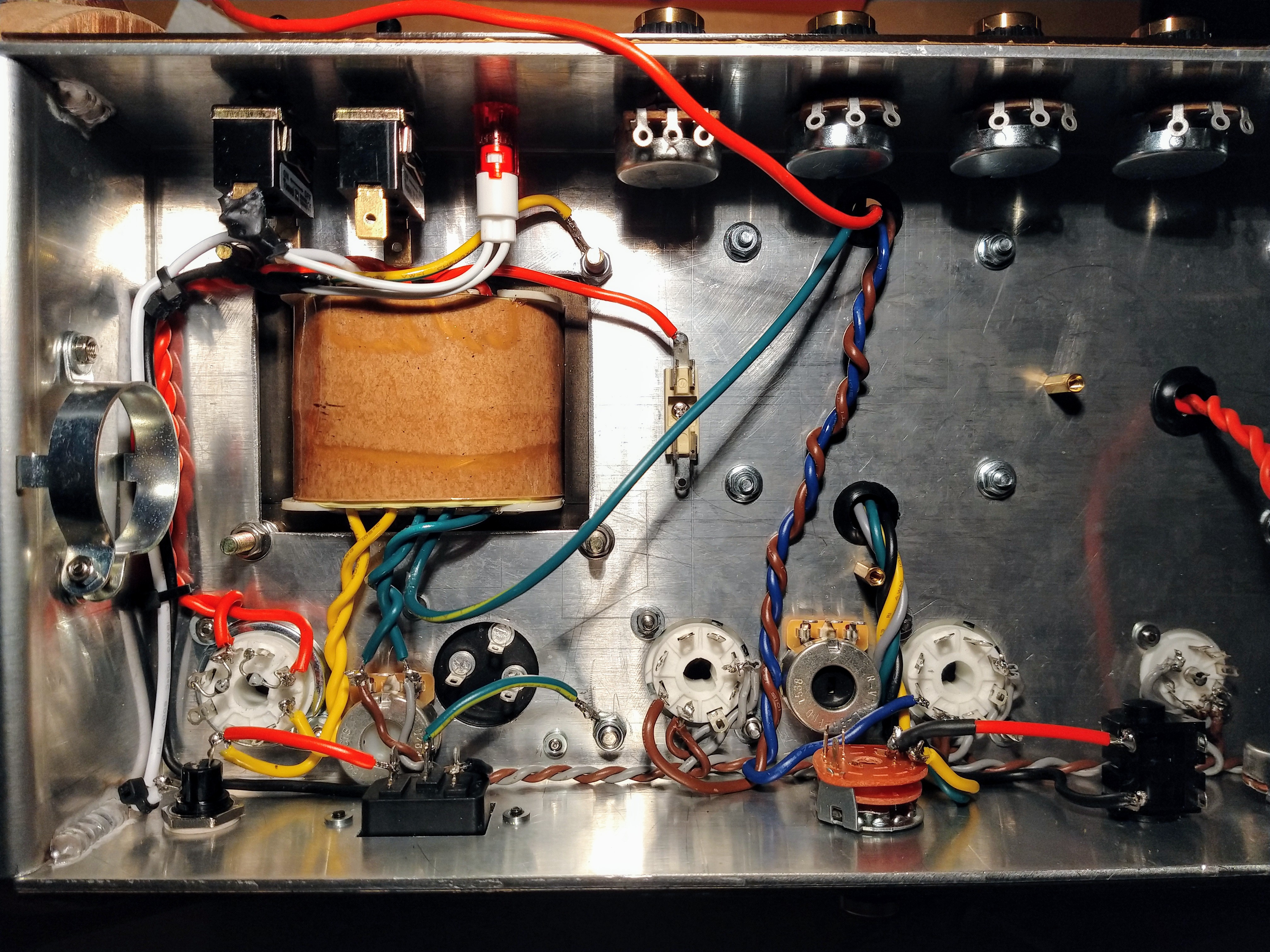
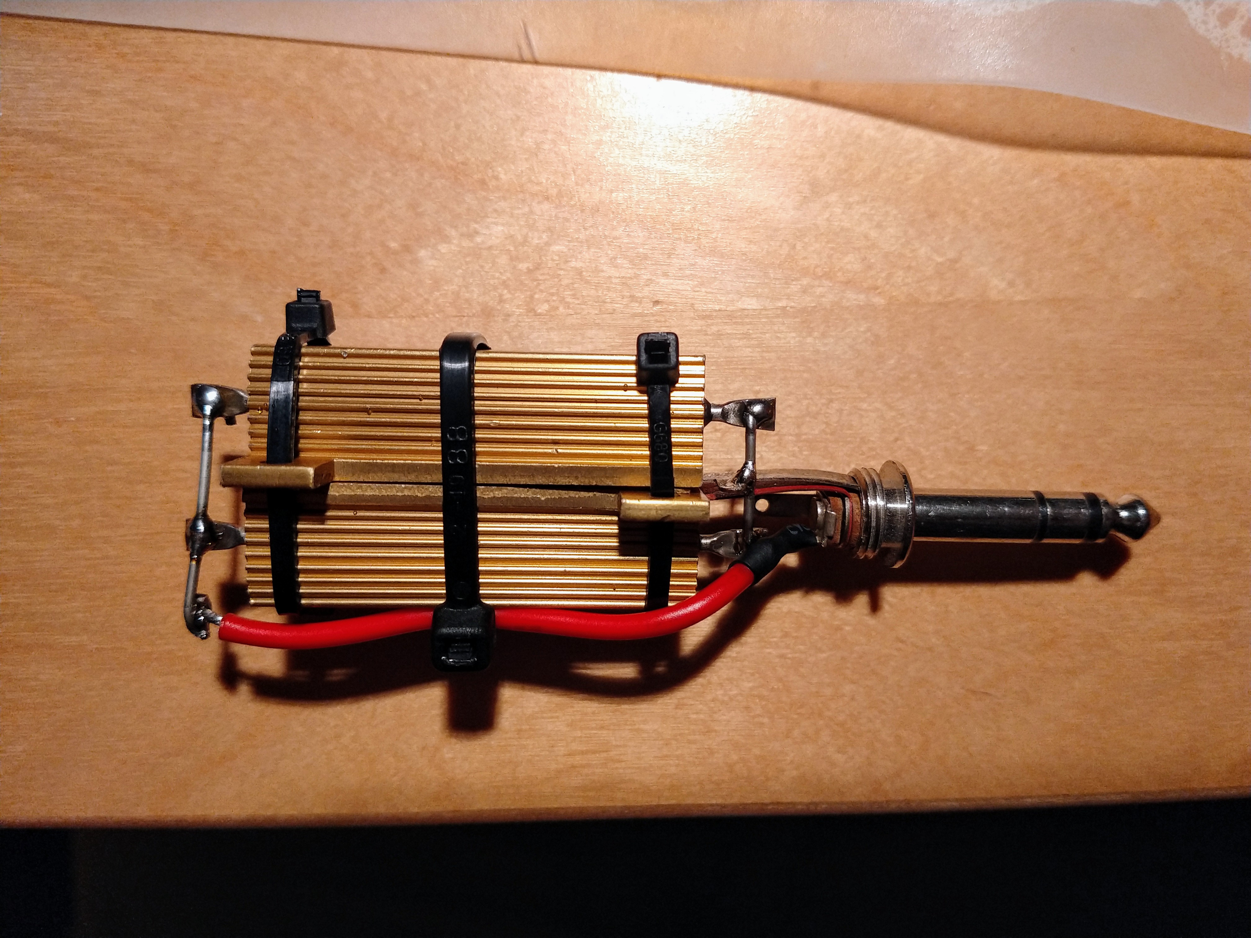
Besides that I made a dummy load:
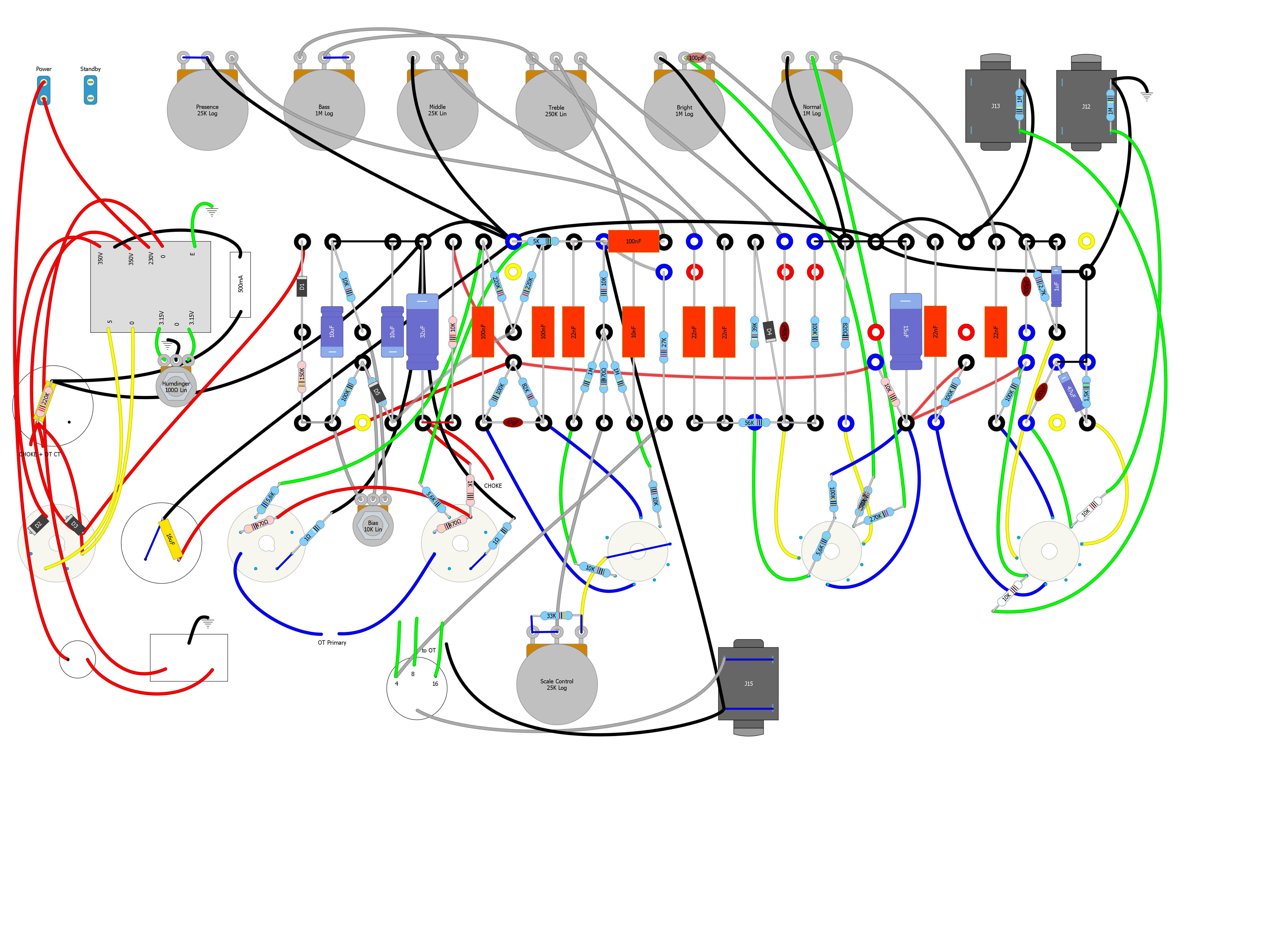
Monday 12-11-2018: Been looking at the layout. Replaced one cap can half with a separate capacitor on the turret board. Looks a lot cleaner. Revisited the grounding scheme; still not happy with the 1M resistors at the input jacks…
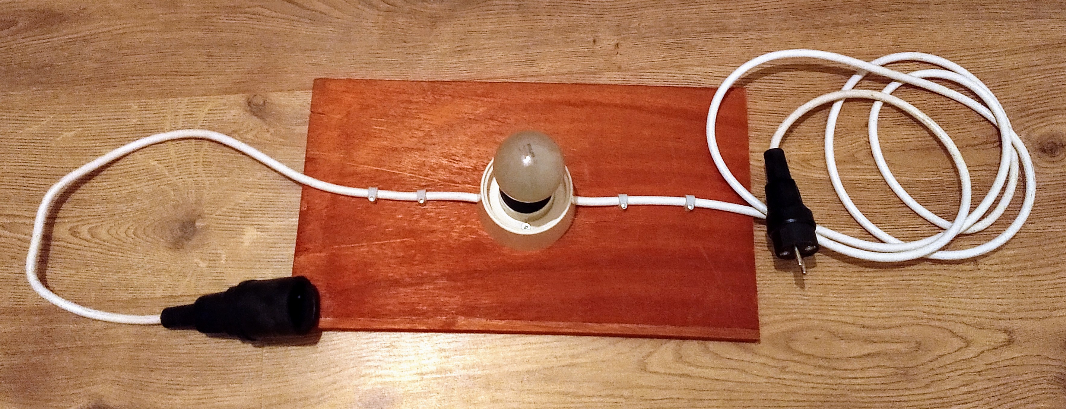
Tuesday 13-11-2018: Made a light bulb current limiter:
Thought about the wire wound grid resistors and the 1M grid leaks. I think I will mount the rectangular wire wound resistors with double sided tape on the chassis. The 1M resistors can that lay on top of them.
I’ve mounted the turret board to see how much space I have for the grid resistors. I needed to enlarge the holes in the turret board with a 3mm drill to be able to put the screws to them.
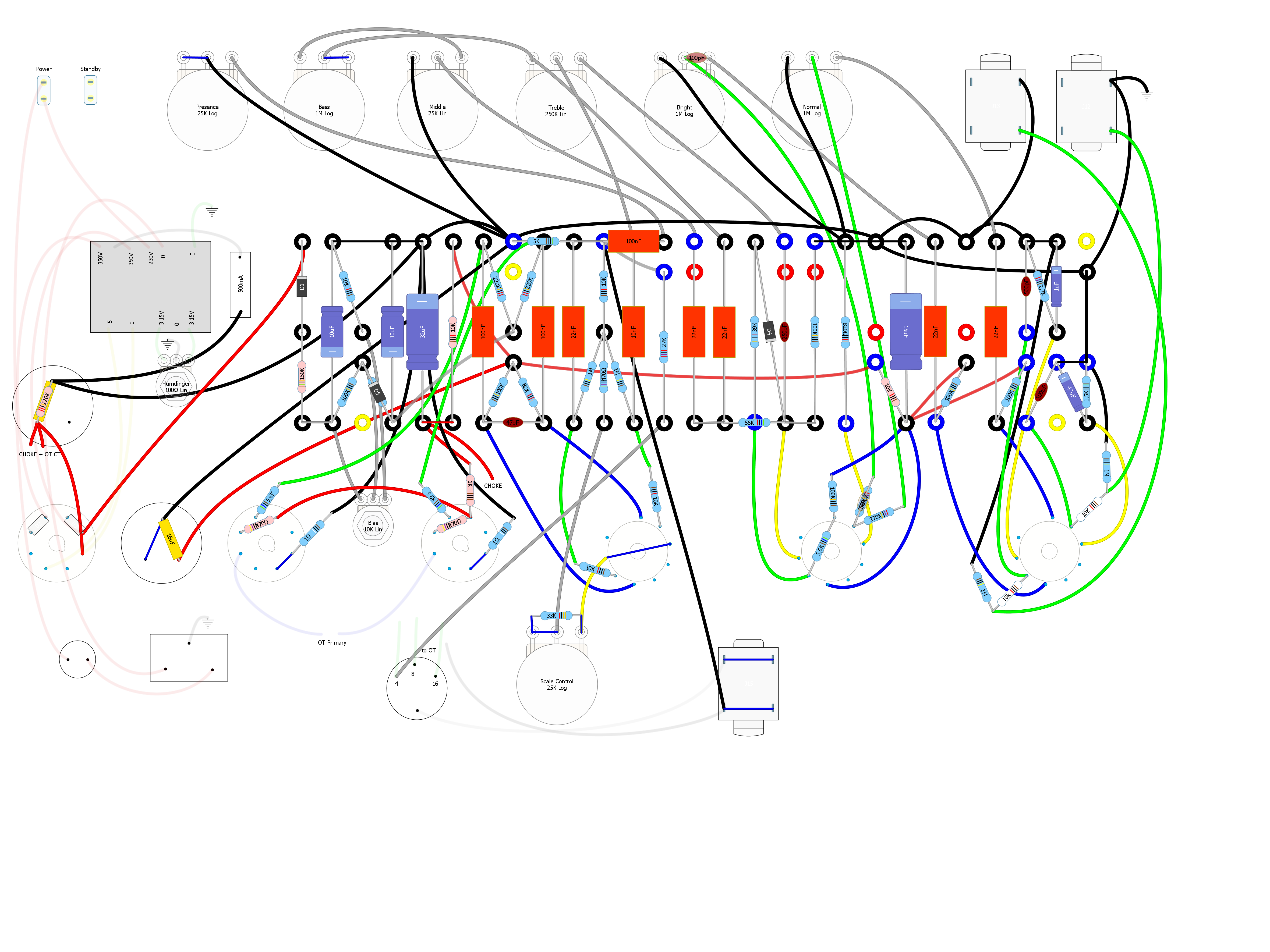
Wednesday 14-11-2018: Indicated in the layout what was mounted/soldered in the chassis using the ‘alpha channel’ of the parts. Also wrote fullAlpha.m to automatically generate the full alpha layout to a newly created .diy file.
Ordered some parts: turrets, wire and a 30uF, 500V cap.
Wednesday 21-11-2018: Have been waiting for parts, but it looks like they arrive tomorrow.
Friday 23-11-2018: Removed and added some turrets. It was cold. Turrets did not ‘bend’ well. I heated them using a burner and they were a bit easier to bend. Swaging tool not perfect. Anvil is a bit short: other turrets touch the nut causing the turrets to be places not completely flush to the surface. Started mounting some components to the turret board.
Saturday 24-11-2018: Finished mounting and soldering the components to the turret board. Soldering is inconsistent. Some seem quite OK, other not so much… One or two turrets just did not ‘accept’ the solder.
A few lessons for the next time:
- Resistors and diodes leads are not long enough to mount around the turrets. Mount the turrets closed to each other in these cases.
- Capacitors are quite a bit larger than in the drawing.
- 47uF capacitor on input cathode is too large (physically) to fit inbetween the turrets.
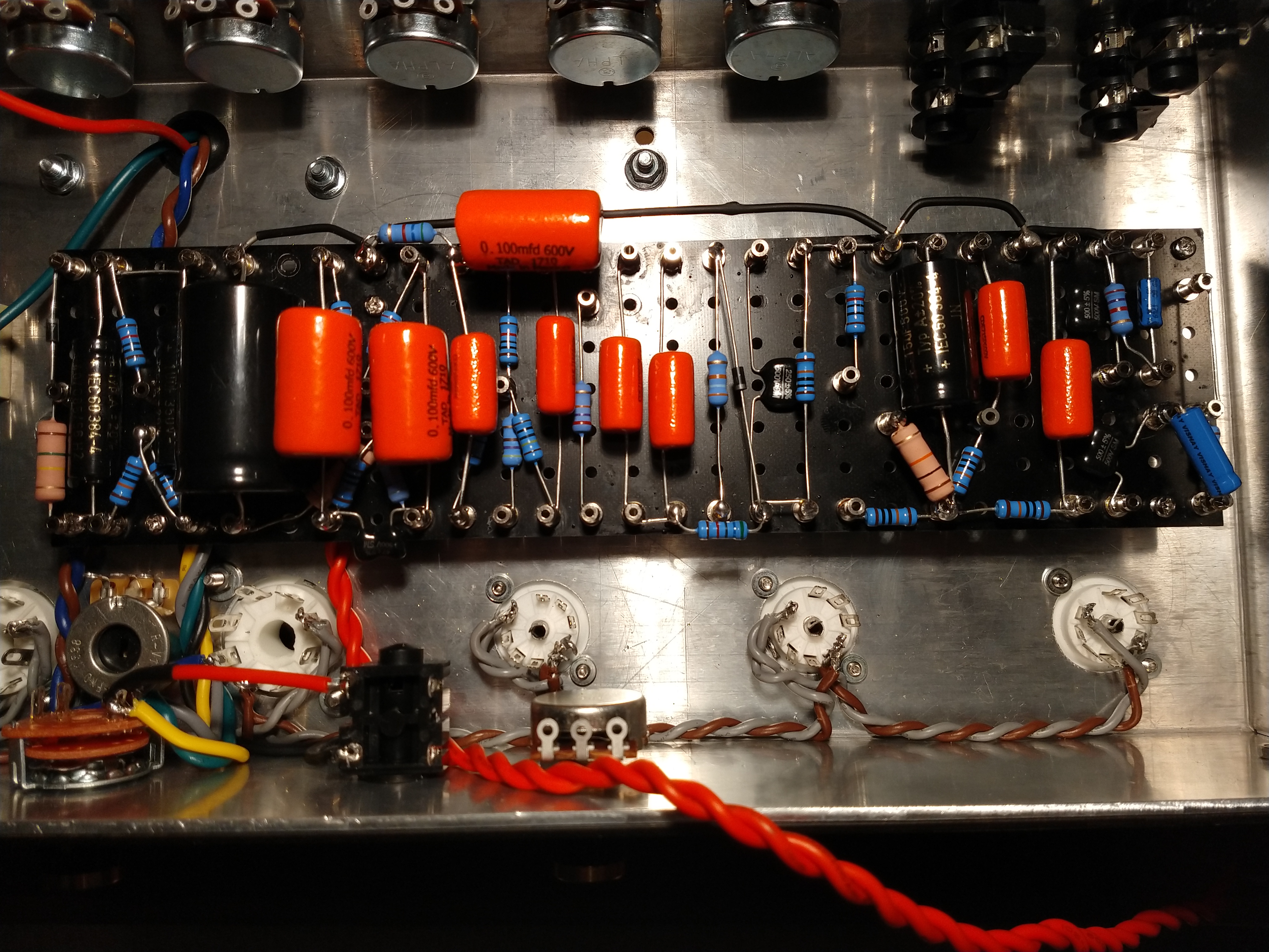
Sunday 25-11-2018: Mounted some extra parts. Did not solder them yet as more connections to these lugs will have to be made. Guess I will determine the wire lengths with the bord in, remove board and attach the wires to be board.
Wednesday 28-11-2018: Cut several wires to length. Put them on a paper sheet with some text above it to indicate where it should go. I Plan to make a nice table here when all are ready.
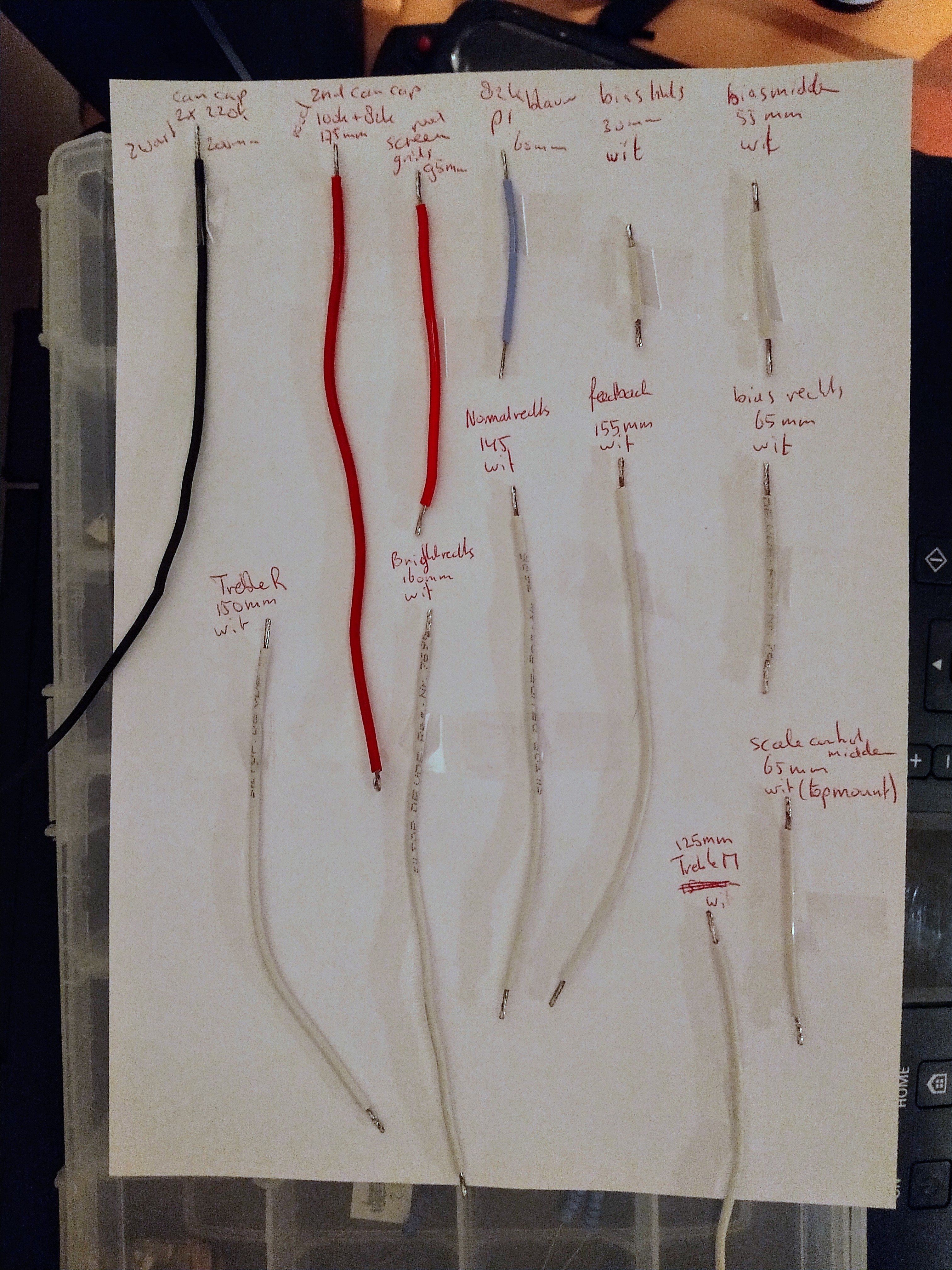
Friday 30-11-2018: Determined most wire lengths:
| Connection 1 | Connection 2 | Colour | Length [mm] | Comments |
|---|---|---|---|---|
| 2nd can cap ground | star ground 2x 220k | black | 195 | |
| 1 Ohm of V5 | ground of 32 uF | black | 120 | |
| 1 Ohm of V4 | ground of 32 uF | black | 100 | |
| 2nd can cap + | 100k + 82k | red | 190 | |
| 100k + 82k | 10k | red | 155 | completely under board |
| V2 pin 3 | 820 Ohm | yellow | 100 | |
| V2 pin 8 | diode | yellow | 65 | |
| V3 pin 8 | scale control right | yellow | 65 | |
| V1 pin 8 | 2.7k Ohm | yellow | 85 | |
| V1 pin 3 | 1.5k Ohm | yellow | 55 | |
| Bright middle | 270k Ohm | shielded | 220 | Optional bright cap |
| Normal middle | 270K Ohm | shielded | 225 | |
| Input 1 | V1 | shielded | 160 | |
| Input 2 | V1 | shielded | 110 | |
| Treble left | 22 uF | white | 155 | |
| Middle Middle | 22 uF | white | 155 | |
| Presence right | 100 uF | white | 230 | |
| Presence middle | star ground 2x 220k | black | 200 | |
| Middle left | star ground 2x 220k | black | 145 | |
| Bright left | 820 Ohm | black | 160 | |
| input 2 ground | other ground | black | 90 | completely under board |
| Normal left | 820 Ohm | black | 150 | |
| input 2 | turret | black | 75 | |
| input 1 | turret | black | 60 | |
| 1M Ohm | input 1 ground | black | 120 | |
| speaker | 10 k | black | 180 | |
| screen grid | screen grid | red | 95 | |
| 82k | V3 pin 1 | blue | 60 | |
| bias left | 100k | white | 30 | |
| bias middle | 100k | white | 55 | |
| bias right | 10k | white | 65 | |
| Impedance selector | 27k | white | 155 | |
| Normal right | 22nF | white | 145 | |
| Bright right | 22nF | white | 160 | |
| Treble right | 250pF | white | 150 | |
| V1 pin 1 | 22nF | blue | 60 | |
| V1 pin 6 | 22nF | blue | 100 | |
| V2 pin 6 | 100k | blue | 130 | |
| V2 pin 1 | 100k | blue | 50 | |
| bias diode | rectifier | red | 210 | |
| V5 pin 5 | 100nF | green | 110 | |
| V4 pin 5 | 100nF | green | 125 | |
| V2 pin 7 | 39k | green | 100 | |
| V1 pin 7 | 250pF | green | 105 | |
| V1 pin 2 | 250pF | green | 55 | |
| V3 pin 6 | 100k | blue | 115 | |
| Treble middle | 10nF | white | 125 | |
| Scale control middle | 470 | white | 65 | top mount |
| bias output | 2x 270k | white | 65 | both connection under turretboard |
| 10k | 27k | white | 35 | both connection under turretboard |
2x ground connection (hum dinger and input jack) to be made.
Saturday 01-12-2018: Soldered all the wires to the turretboard.
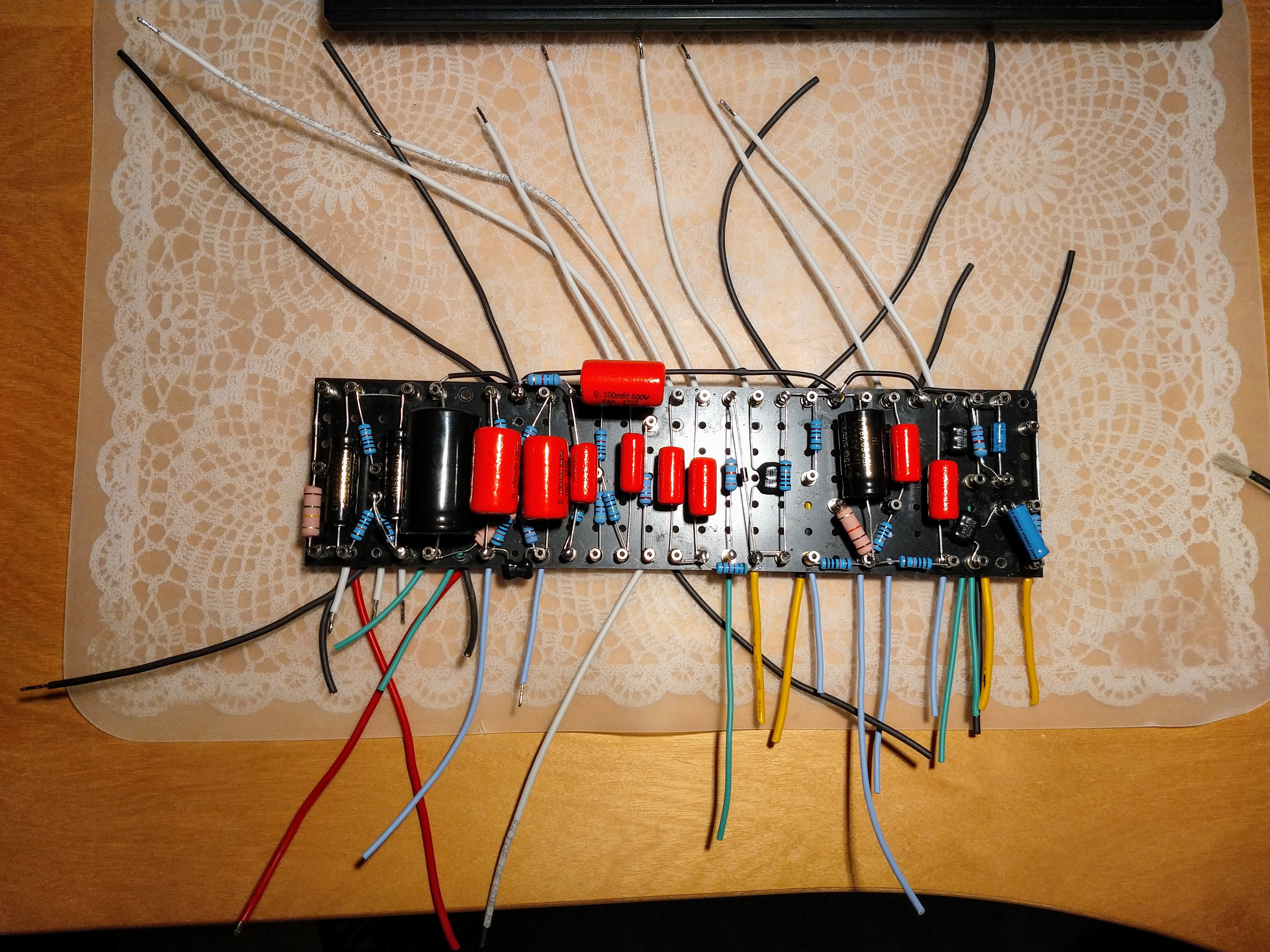
Sunday 02-12-2018: Soldered the input shielded wires.
Monday 03-12-2018: Soldered the volume pots shielded wires and mounted the turretboard and dry-fitted all wires. No obvious errors, but should check connectivity.
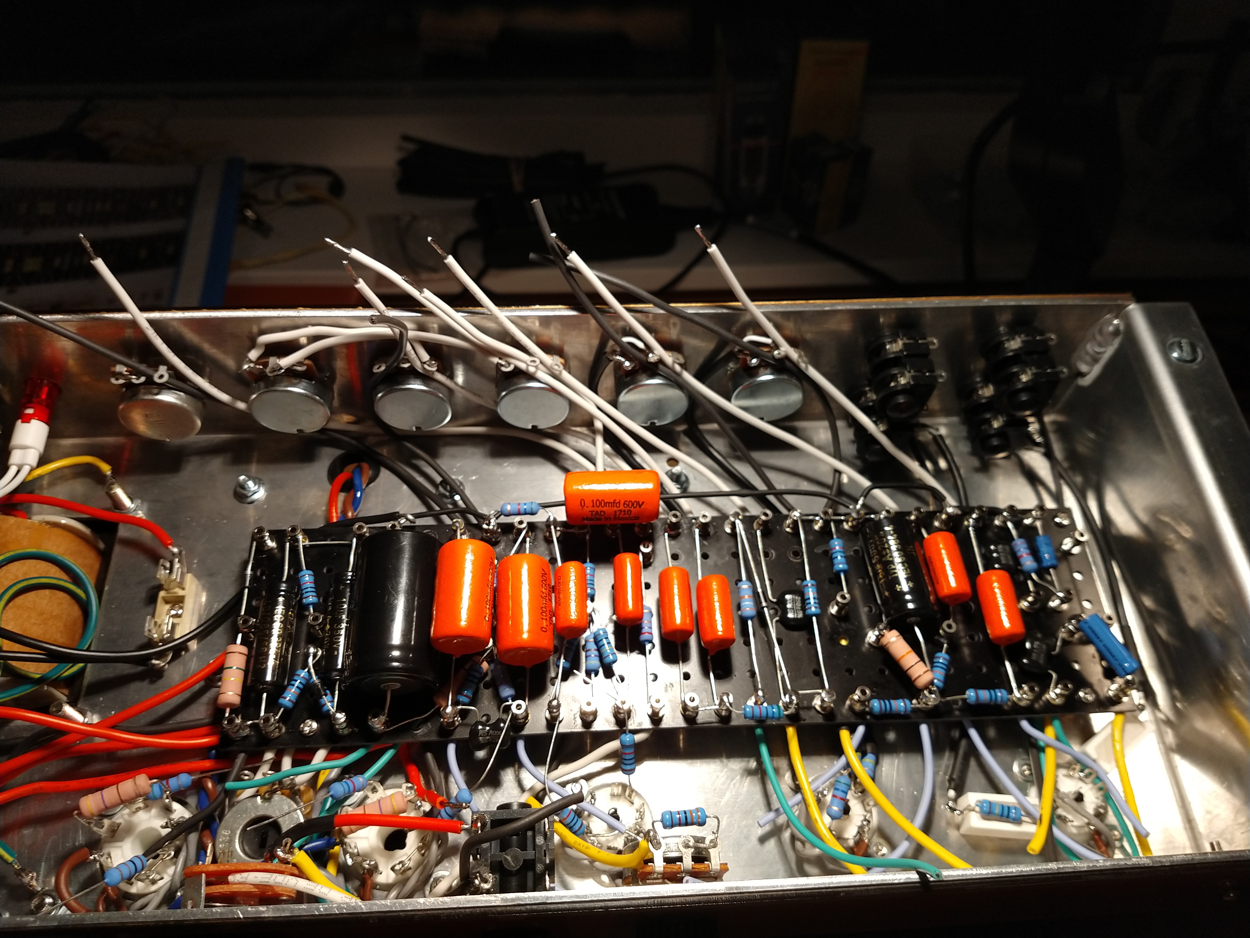
Tuesday 04-12-2018: Checked all wires whether they are connected to the right turrets: all OK.
Wednesday 05-12-2018: Soldered (most of) the input side.
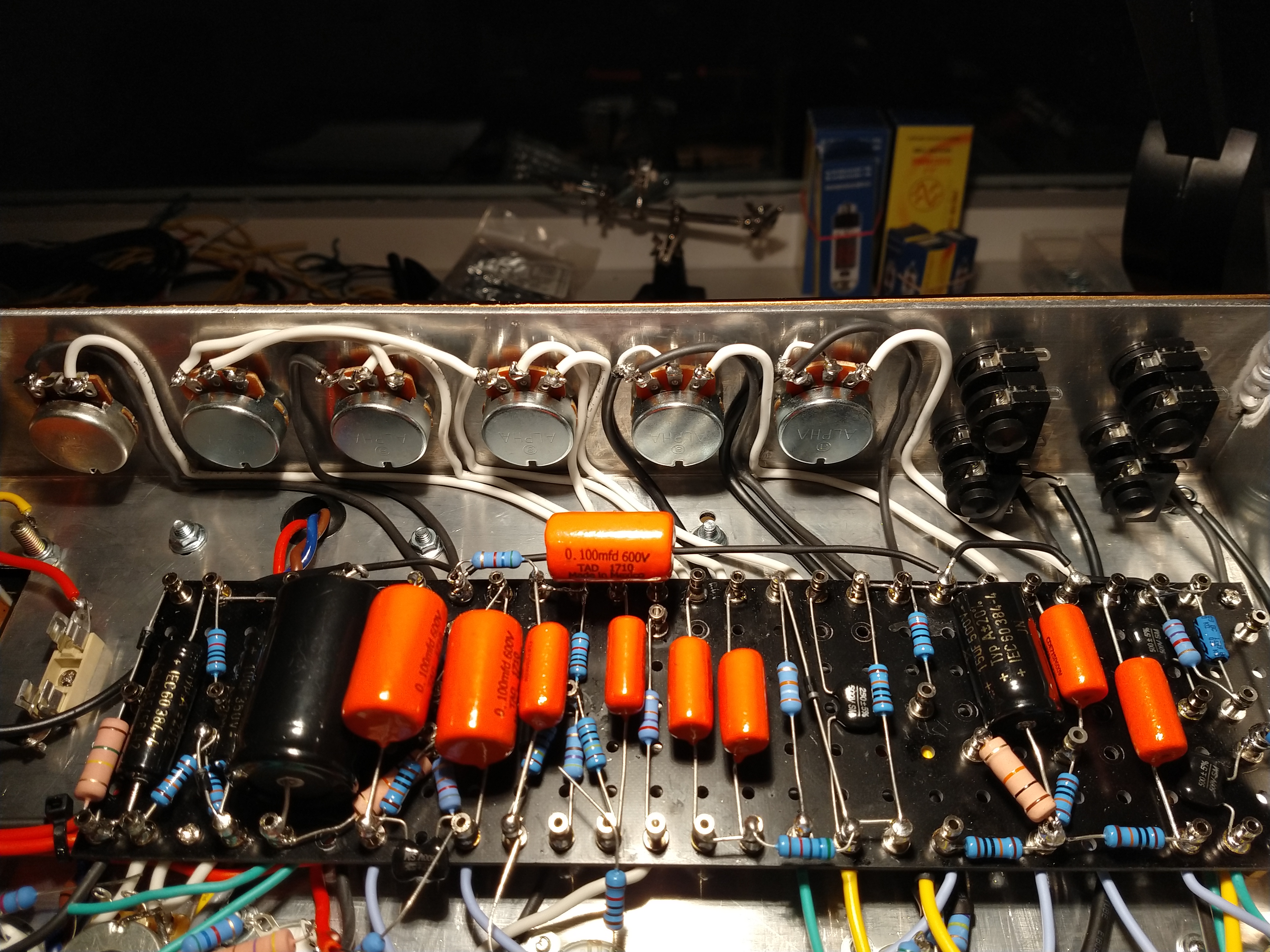
Thursday 06-12-2018: Soldered the preamp tubes. Not as neat as I wanted to. Holes are quite small and there’s a lot happening on a small area. Input grid stoppers are also quite big. Heater wires around the pins also make things a bit crowded. Next time try a bit harder to have the heater wires go over the center of the sube socket per Blencowe. Perhaps even use a smaller gauge wire.
Friday 07-12-2018: Soldered everything. Started up according to Rob Robinette’s page. Found that the bias was not grounded and the bias dropping resistor was too large. Fixed that, but the amp oscillates with every pot set to zero. Seems to be around the cathode follower.
Saturday 08-12-2018: Troubleshooting continued, but the problem persists.
Findings:
- When I ground the gridstopper of the ltpi, the output is low.
- When I bypass the tone stack, the output is high.
- Looking at the signal over the 820 Ohm cathode resistor just before the cathode follower it looks ok.
- Without the first preamp tube the problem exists.
- Swapping tubes did not help.
- Disconnecting feedback did not help.
Below is a voltage chart with the power tubes removed grid V3a grounded:
| tube | pin 1 [V] | pin 2 [V] | pin 3 [V] | pin 6 [V] | pin 7 [V] | pin 8 [V] |
|---|---|---|---|---|---|---|
| V1 | 220 | 0 | 1.5 | 244 | 0 | 2 |
| V2 | 191 | 0 | 1 | 325 | 191 | 192 |
| V3 | 375 | 0 | 18 | 200 | 10 | 18 |
Max. bias: -43V
Connected scope at the grid stoppers of the (removed) output tubes. Pre amp seems to work just fine (?!). Volumes work, humdinger works, bass pot works (probably 50Hz noise, didn’t check).
Sunday 09-12-2018: New day, new result.
I swapped preamp tubes and measured the plates of the phase inverter again: No strange results. But the old ltpi tube seems to work ok in another position. Weird.
I put the power tubes back in and the problem (oscillations with all pots down) is still present. I jumpered the two signals going to the grid stoppers of the output tube, just like the trainwreck type 3 Master Volume from @robrob ‘s site with the volume all the way down. The output is fine in this situation. I connected my scope to the plates of the LTPI and both show a nice sine wave that distorts at higher volumes (smart phone as signal generator). Gone through the frequency range: OK. Volume, treble, middle, bass, scale control all seem to work just fine.
Here is a (bad) image of the scope showing the signal:
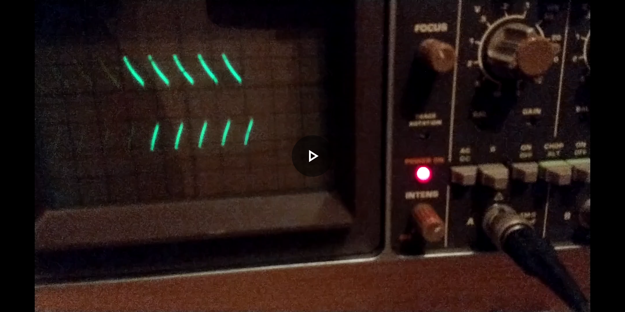
Scope is set a 2V/div and 10ms/div. If my math is correct the frequency is just over 100Hz and the peak-to-peak amplitude is a little over 6V into an 8 Ohm dummy load.
Monday 10-12-2018: Injected 400Hz signal with smartphone on advice of Rob Robinette.
Ok, I did that. But I don’t know what to say. No clear conclusion.
I did the test with the jumper in place. I can use a large signal and than everything is fine up to and including the ltpi. If I use a small signal I see some (50Hz) signal superimposed on the 400Hz signal. This 50Hz signal increases further up the signal chain. I also found that everything is somewhat microphonic (even if I tap the table) with the oscilloscope set very sensitive. Tapping the tubes it seems to be worst for one of the output tubes.
If I remove the jumper the problem starts again and I can hear the noise/hum although I’m using a dummy load. The light bulb current limiter also starts glowing quite a bit brighter.
ps. It’s just an image, not a movie.
Tuesday 11-12-2018: Thanks to @robrob ‘s remark about the wrong tube wiring I’ve been checking all connections and components again. I found a resistor that was much less than what it should be (~10 Ohm i.s.o. 5.6k). I removed the resistor and measured it: 5.6k. Something else was off and then it struck me: Eureka!
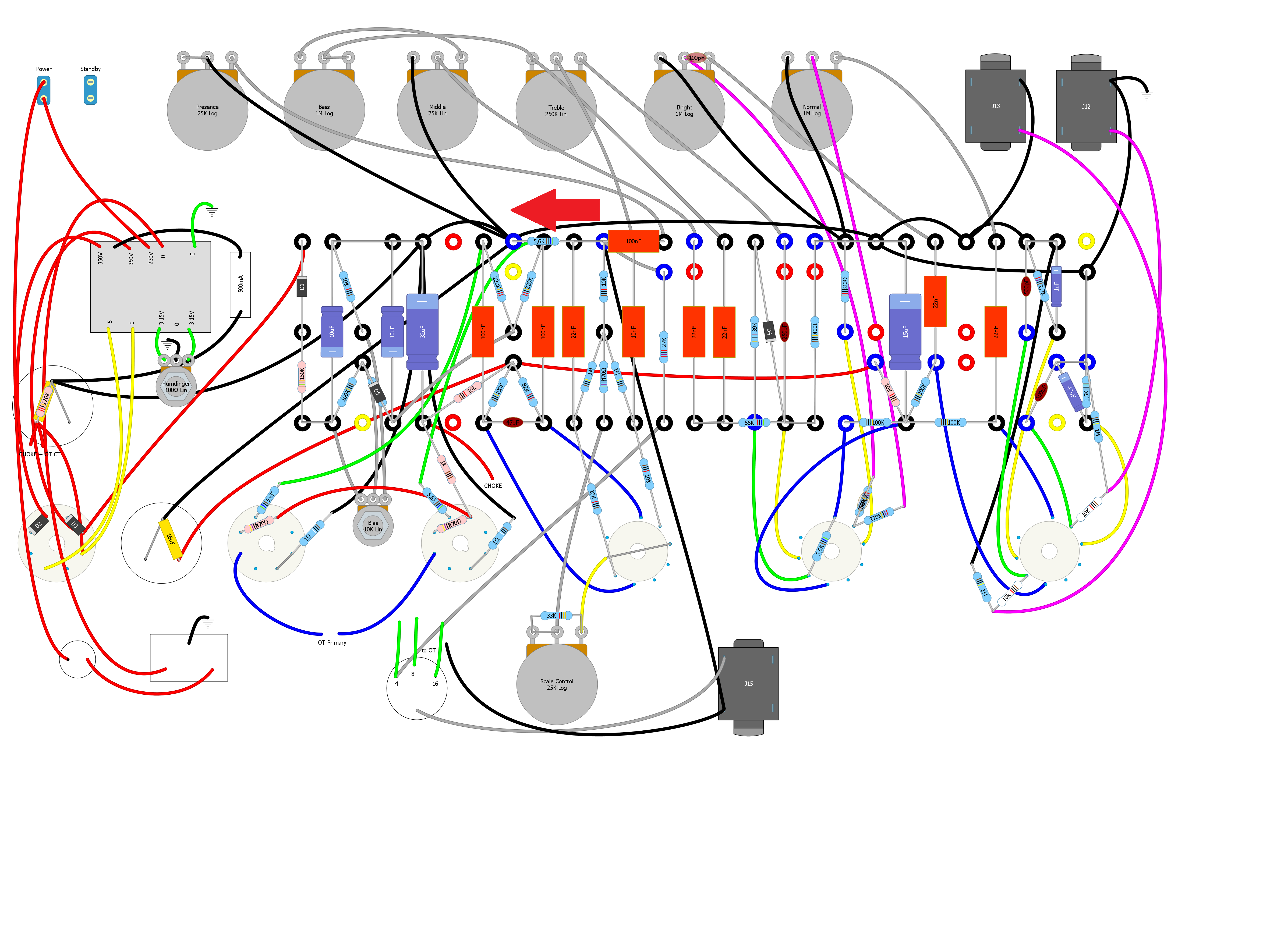
The speaker ground should be moved to the local star ground at the blue turret!
I’m going to change that. It’ll be a hassle as it under the board…
I’ll keep you posted.
Yes! That was the problem. Thanks everyone for the help so far!
Still not happy though. I think the phase splitter is clipping to hard. Especially on the grid with the feedback attached, where it almost look like only one half of the sine wave is present. Previous stages show a nice rounding of the sine peaks on both sides.
It will have to wait to tomorrow evening. These day time jobs take up too much time…
Wednesday 12-12-2018: Yes! It’s working! Can’t really test it as the kids are asleep. That will have to wait until the weekend.
I resoldered the impedance selector and output jack. It might have had a short somewhere…